Blaine Western & Michael Parr
company
08 Dec 2012 — 19 Jan 2013
Configuraion #1, 2013
Photo credit Blaine Western
Configuraion #1, 2013
Photo credit Blaine Western
Configuraion #1, 2013
Photo credit Blaine Western
Configuraion #1, 2013
Photo credit Blaine Western
Configuraion #2, 2013
Photo credit Blaine Western
Configuraion #2, 2013
Photo credit Blaine Western
Configuraion #3, 2013
Photo credit Blaine Western
Configuraion #3, 2013
Photo credit Blaine Western

Configuraion #3, 2013
Photo credit Blaine Western
Configuraion #4, 2013
Photo credit Blaine Western
Configuraion #4, 2013
Photo credit Blaine Western
Configuraion #4, 2013
Photo credit Blaine Western
Configuraion #5, 2013
Photo credit Blaine Western
Configuraion #6, 2013
Photo credit Blaine Western
Configuraion #7, 2013
Photo credit Blaine Western
Configuraion #7, 2013
Photo credit Blaine Western
Configuraion #7, 2013
Photo credit Blaine Western
Configuraion #7, 2013
Photo credit Blaine Western
Configuraion #8, 2013
Photo credit Blaine Western
Configuraion #8, 2013
Photo credit Blaine Western
Configuraion #8, 2013
Photo credit Blaine Western
Opening Saturday 8 December, 2pm
Artist talk with Elle Loui August Saturday 8 December, 1pm
In a gesture enfolding a series of events and offsite propositions, Auckland artists Blaine Western and Michael Parr offer a plurality of movements and spatial modes within The Physics Room’s Tuam St premises as it is undergoing reconfiguration.
Alluding to alterations in potential inhabitation and to a softening distinction of private and social attitudes within the exhibition cycle, the project will develop in negotiation with the formal and material limitations of the planning process and in reference to local historical architectural events.
The Physics Room and the artists welcome your presence at the Tuam St premises during the installation period of 30 November to 7 December 2012.
A publication made in collaboration with Christchurch designer Matthew Galloway will be available at the closing of the exhibition, and the associated offsite project neither a window opening or wall will open early in February.
company, neither a window opening or wall and the performance project 1/3 were conceived as a series of unfolding relationships and gestures which were developed by the artists and Elle Loui August over 2012-2013.
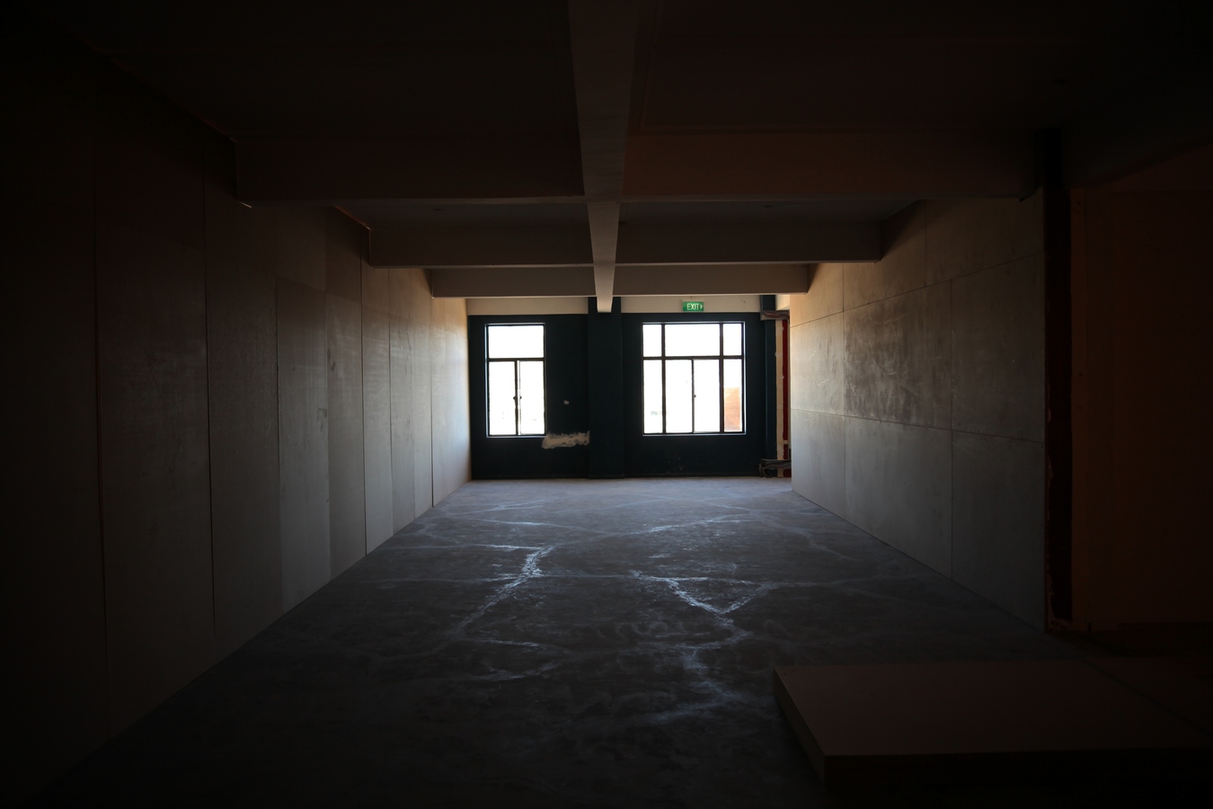
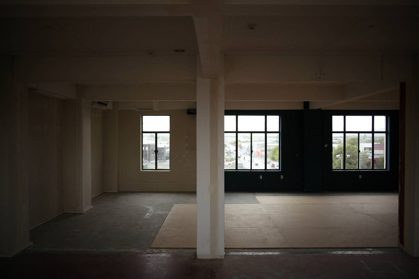
Public Notice #1: 1/12/12
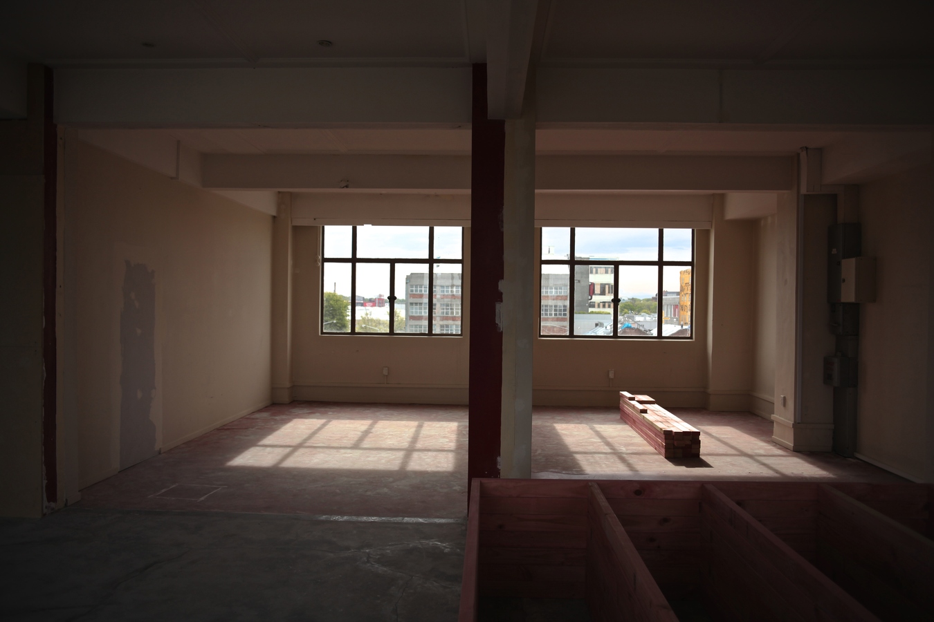
Configuration #1: To support a wall centre, west and rear of the building.
First, in process of constructing the new plan for The Physics Room, Level 3, 209 Tuam Street; the red wall with 5 small apertures, the red aluminium joinery both to the right as enter and to the rear of the room are removed. The frame of the doorway between the kitchen and the back room is to be closed with gib. 30 sheets of 9mm mdf, 5 sheets of 18mm mdf and 250 meters of 90x45mm framing is purchased and delivered. Frames are constructed to span between the concrete columns to support a wall center, west and rear of the building.
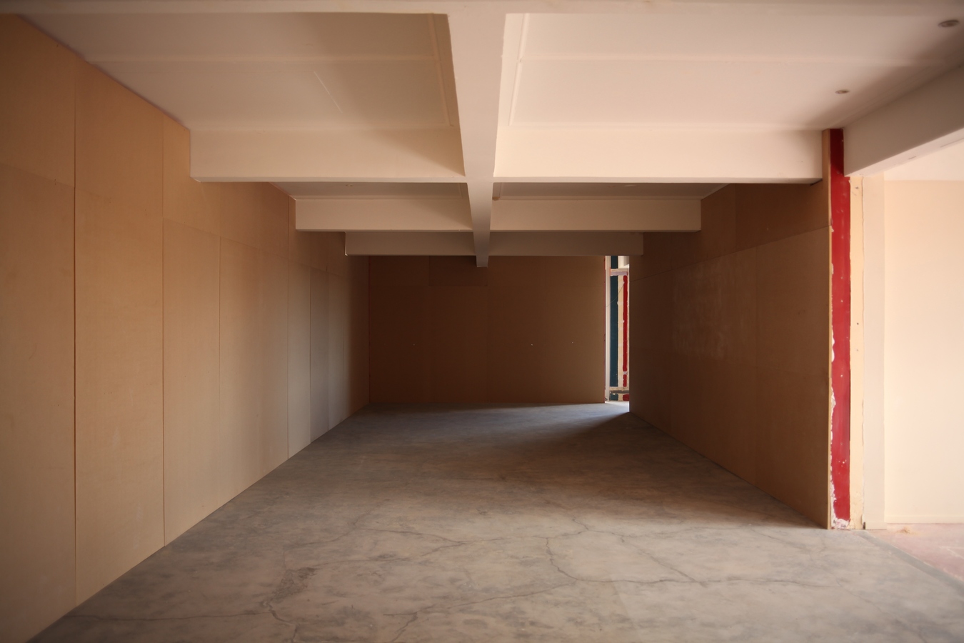
Public Notice #2: 2/12/12
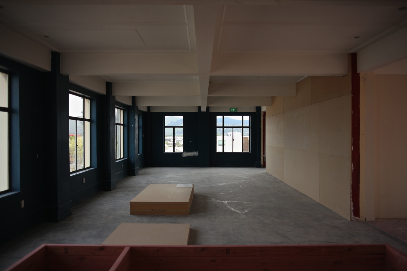
Configuration #2: A continuation of the existing central wall.
2 of the 7 frames are employed to allow a continuation of the existing central wall. The frames enclose the floors longest length into a singular volume roughly half the size of the buildings floor plan.
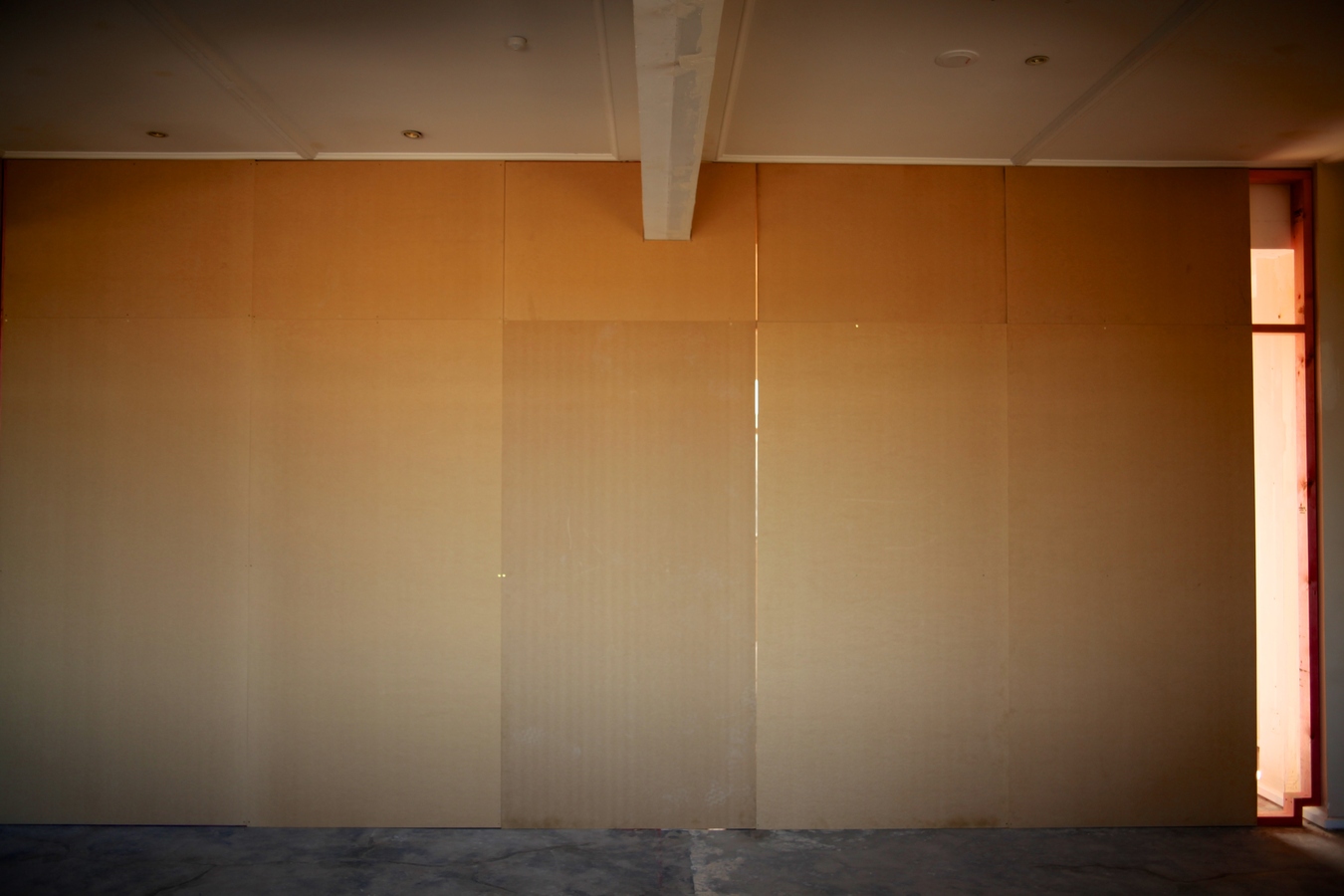
The wall is clad with 6 of the 30 sheets of 9mm mdf restricting both the afternoon sun and any view to the west of the city.
Public Notice #3: 3/12/12
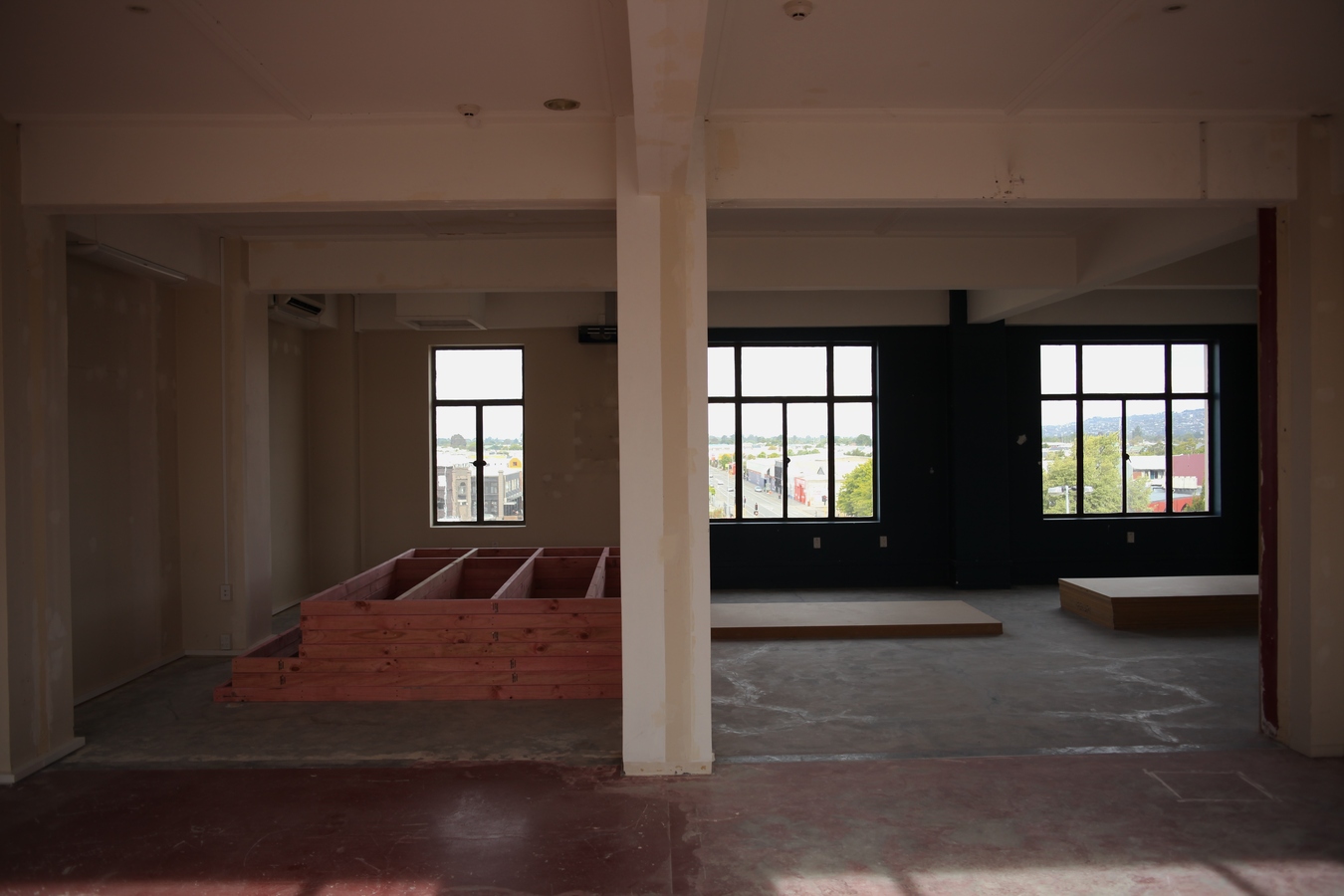
Configuration #3: Perpendicular to the existing span.
Leaving the continuation of the central wall intact, an additional two frames are employed perpendicular to the existing span. One to the west extends the path of the entry as you enter the room. One to the east segments the existing volume roughly in half.
Public Notice #4: 4/12/12
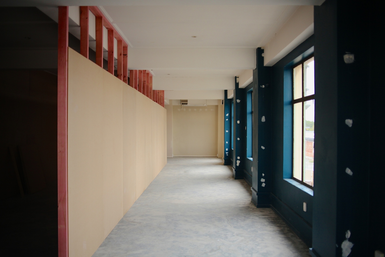
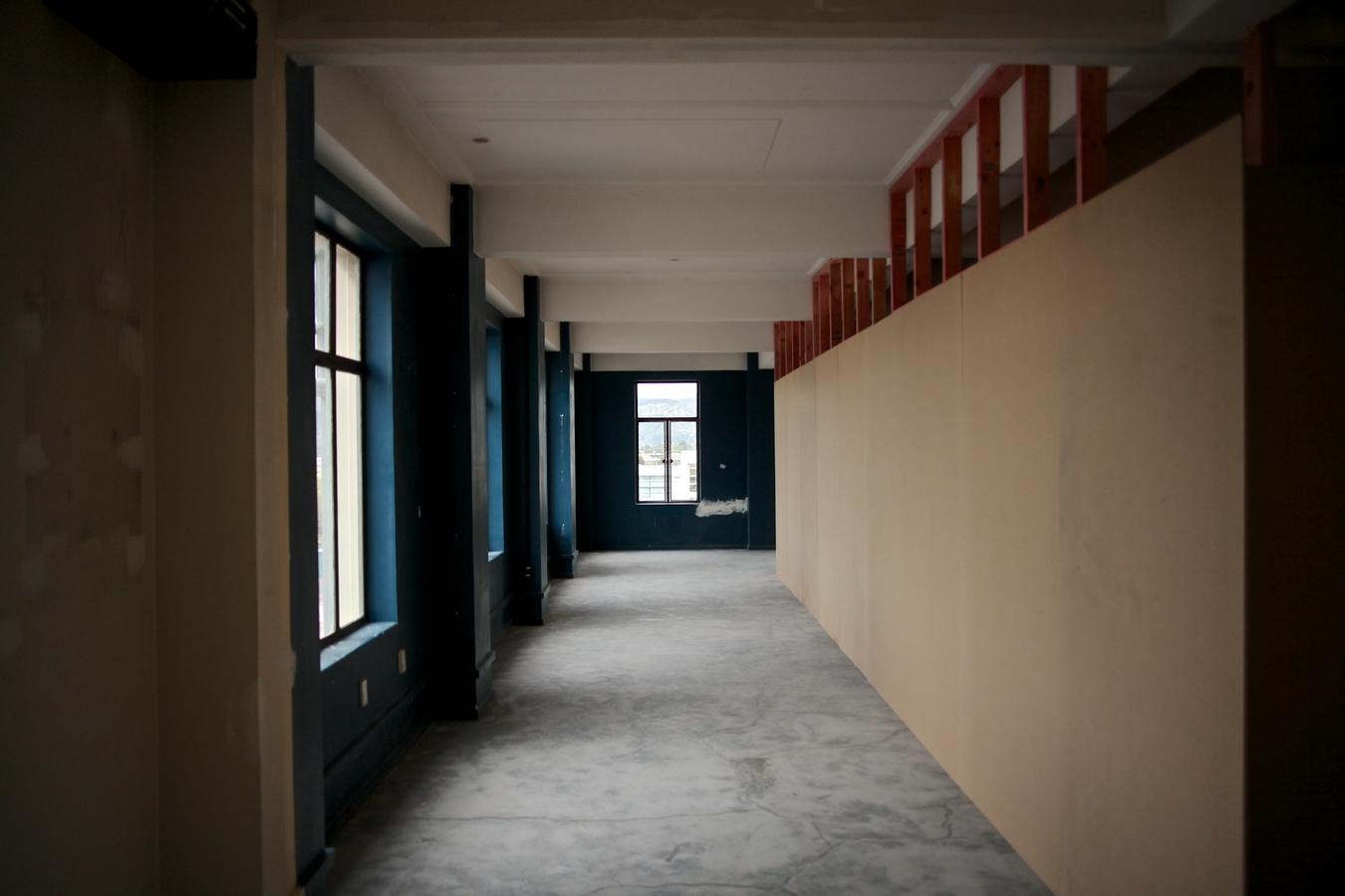
Configuration #4: The cladding suggests a promenade.
The wall that extends the path of entry is left in position. The two frames acting as the continuation of the central wall and the frame dividing the main volume in half are both collapsed. 3 of the longer frames are set in place running parallel with the central wall, approximately center of the largest and longest volume. The remaining 3 are set perpendicular, center of the smaller volume. The frames are clad using 20 sheets of 9mm mdf that face outward creating a corridor roughly 2.5 meters wide between the wall surface and the window. The total floor area has been reduced to half and besides the small openings between the frames, the orientation of the cladding suggests a promenade around the perimeter of the plan and the view of the city becomes the imperative.
Public Notice #5: 5/12/12
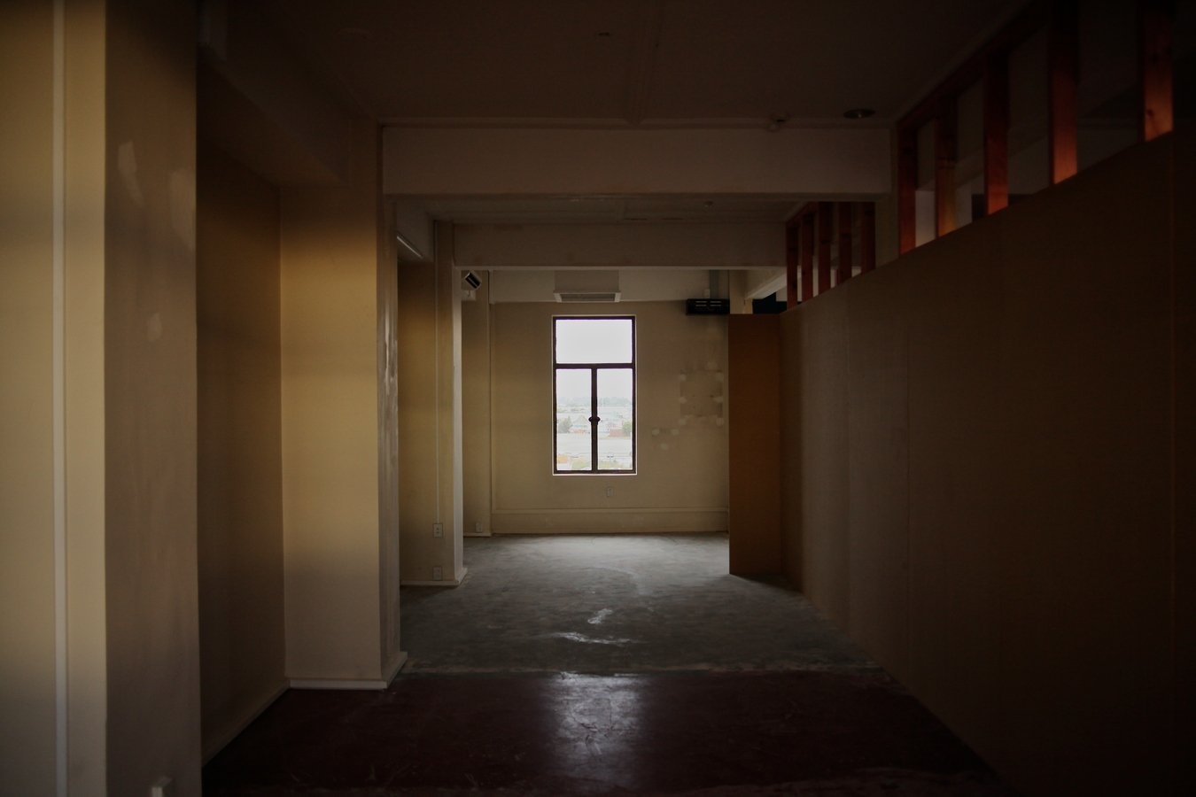
Configuration #5: 600mm from the window sill.
The mdf is removed from the seven walls and all but the three larger frames articulating the longest portion of the corridor are collapsed. These three frames are then pushed outward and placed in front of the windows. Two of the remaining four frames are then placed either side of the middle three and the further two are set in front of the west facing windows. All frames are to be set in place 600mm from the window sill. When fixed, the frames are lined from floor to ceiling using 28 sheets of 9mm mdf. The lined wall disrupts both the views to the east and west of the city while also dramatically reducing the amount of direct sunlight during opening hours.
Public Notice #6: 6/12/12
Configuration #6: In anticipation of the final configuration.
The two frames blocking the windows in the smaller volume are collapsed. In anticipation of the final configuration and to allow the frame to fit 600mm out from the windows on the southern side, the shorter frame is modified so it can pass beneath the concrete beam on the ceiling while also fitting around the existing conduit on the wall. The frames are set in place, maintaining the 600mm distance from the window sill and butted up against the wall from the previous arrangement. The frames are then clad with 6 sheets of 9mm mdf. As you enter, the space between the window and the wall is visible. Direct light is blocked until roughly 1pm when the sun starts to pass over the western side of the building illuminating the smaller volume.
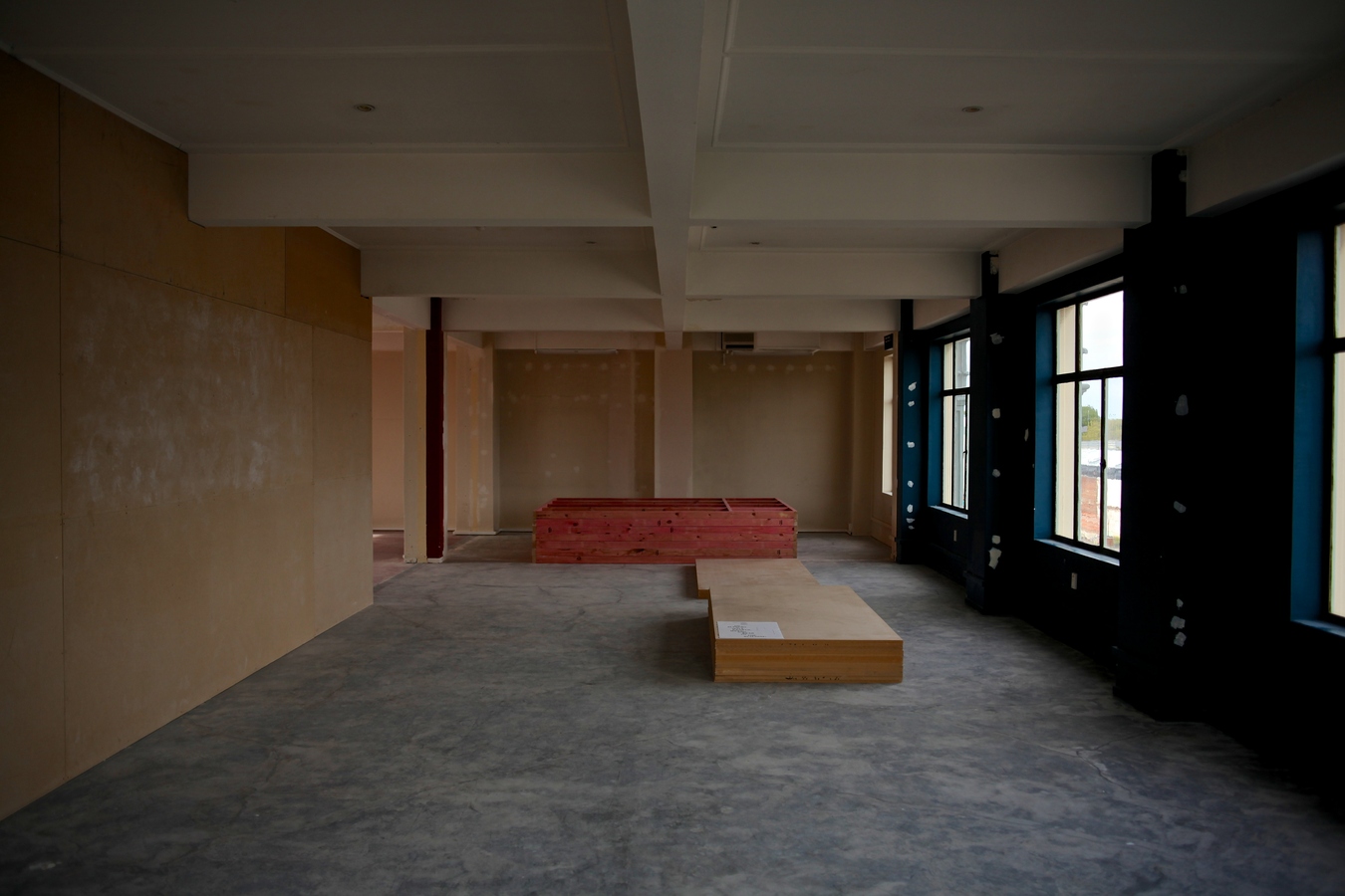
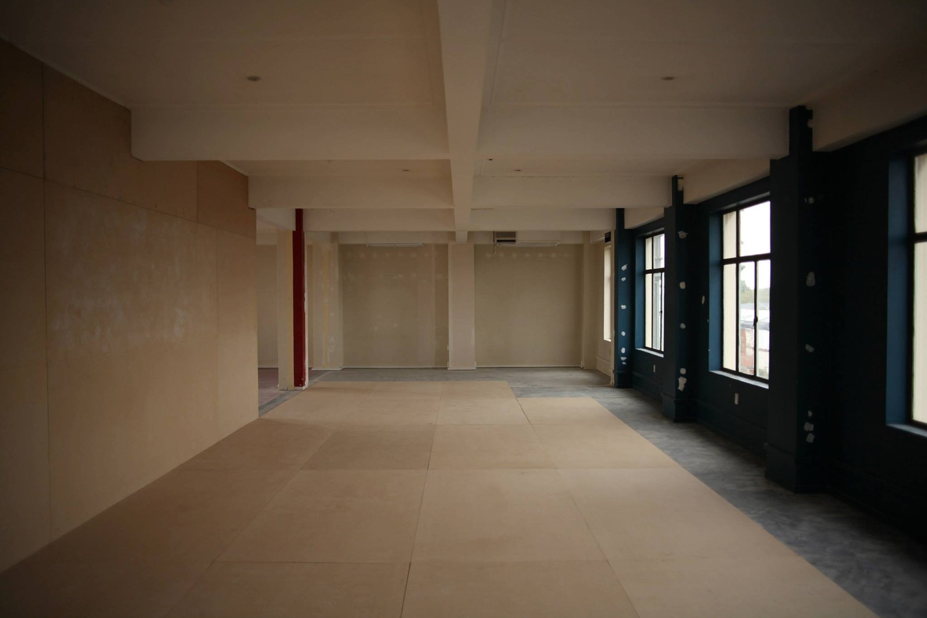
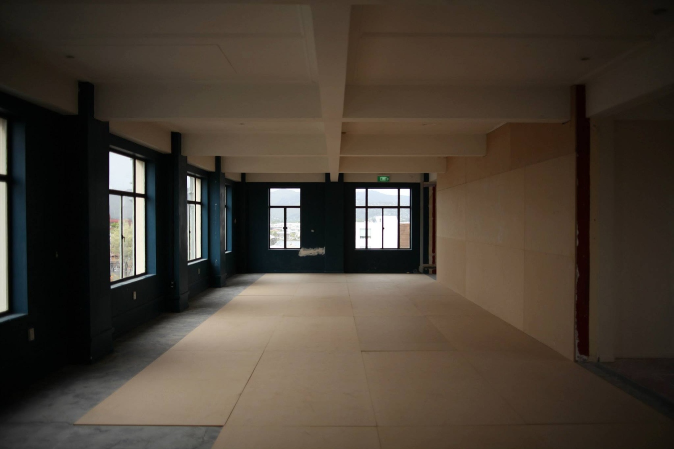
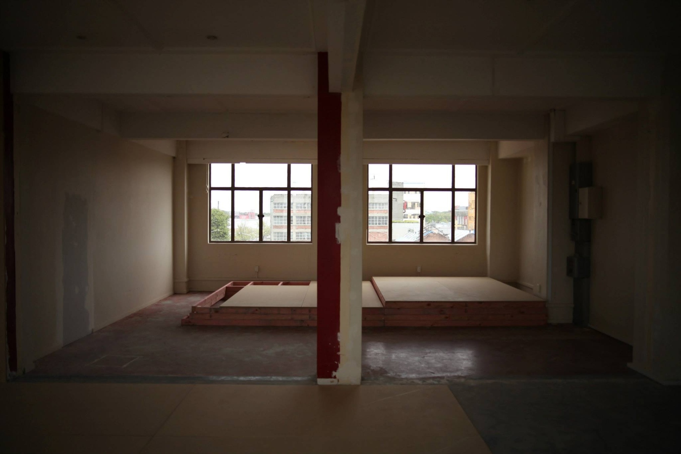
Public Notice #7: 7/12/12
Configuration #7: A floor lining of approximately 60 square meters.
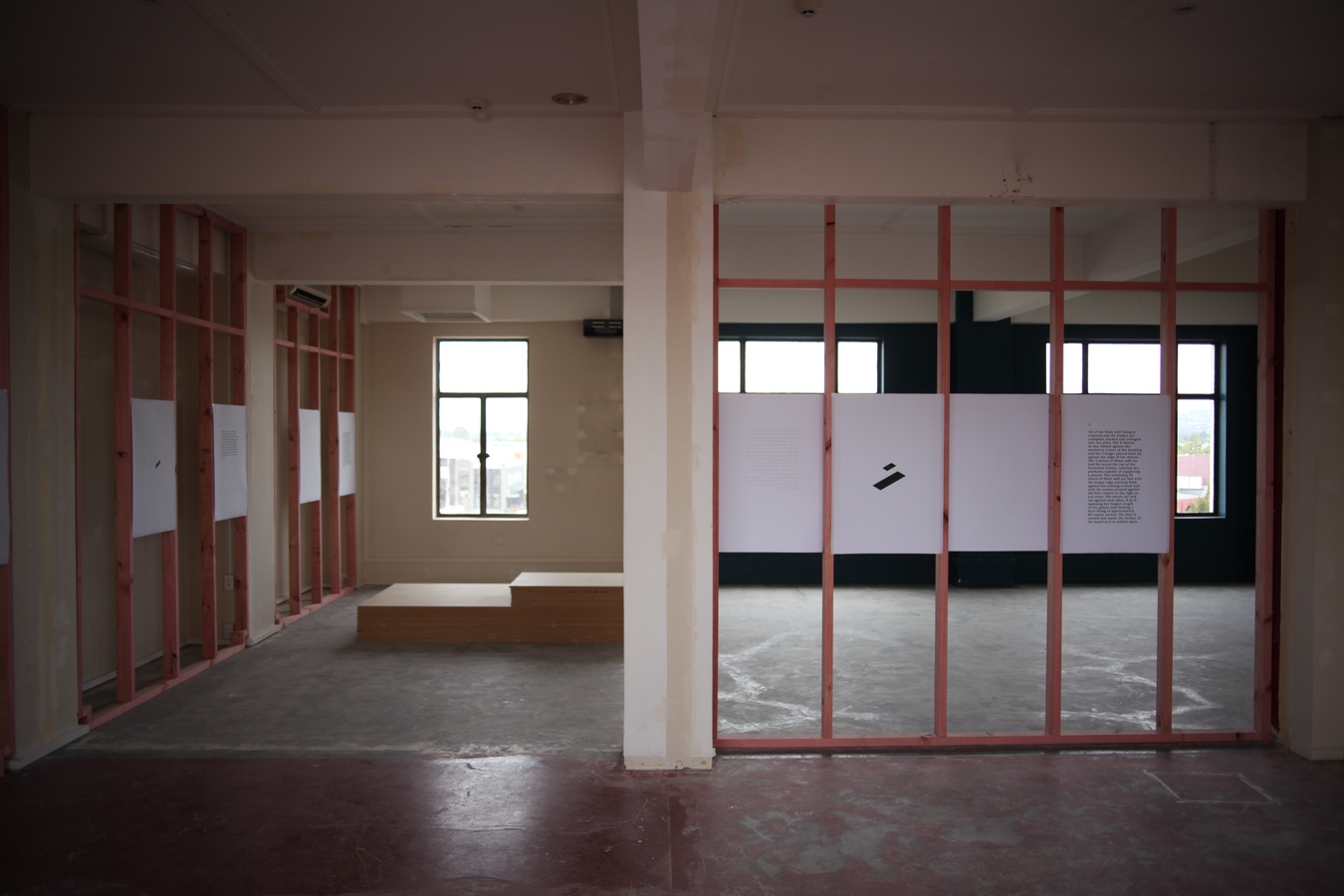
All of the 9mm mdf lining is removed and the frames are collapsed, stacked and arranged into two piles. The 4 shorter in one, butted against the northwest corner of the building and the 3 longer placed hard up against the edge of the shorter. The 5 sheets of 18mm mdf are laid flat across the top of the horizontal frames, creating two platforms capable of supporting a person. The remaining 25 sheets of 9mm mdf are laid with the longer edge running flush against the existing central wall with the corner pressed against the first column to the right as you enter. The sheets are laid out against each other, 4 by 6, spanning the longest length of the gallery and forming a floor lining of approximately 60 square meters. The dust is carried and marks the surface of the board as it is walked upon.
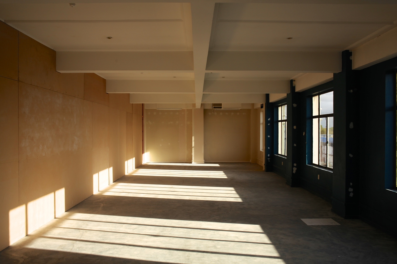
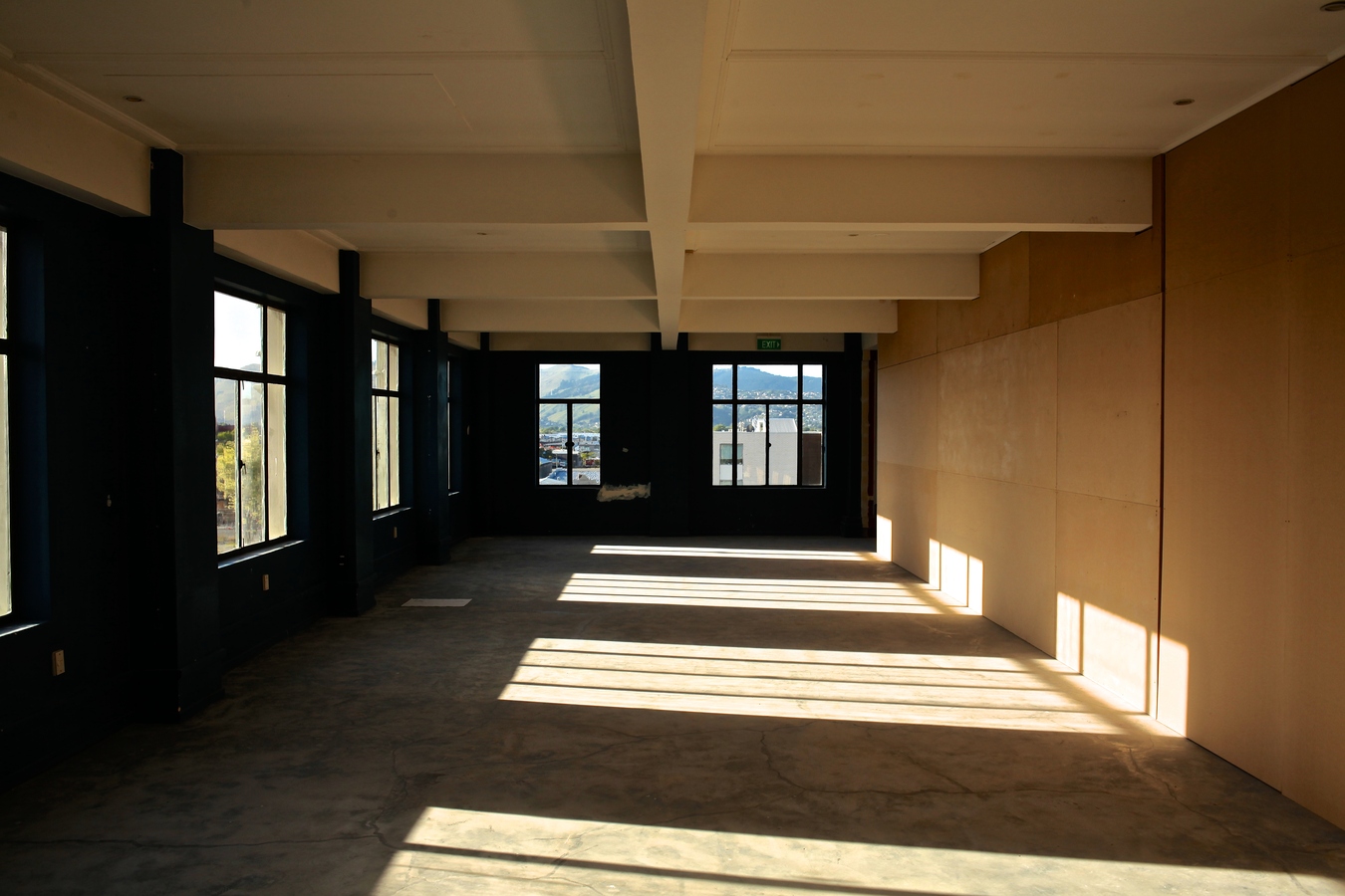
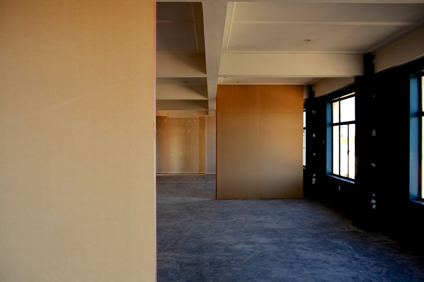
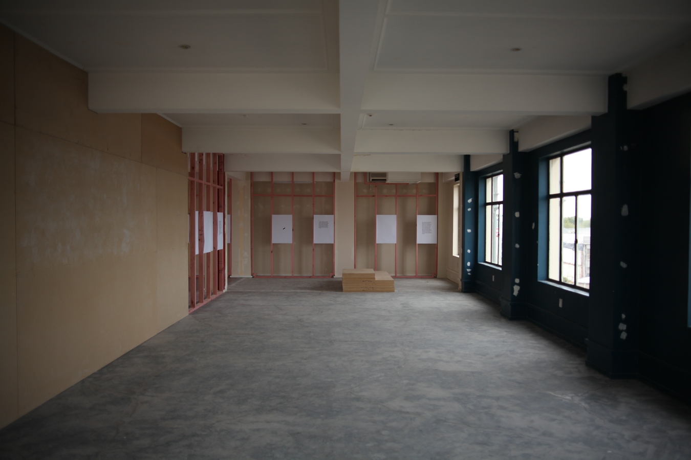
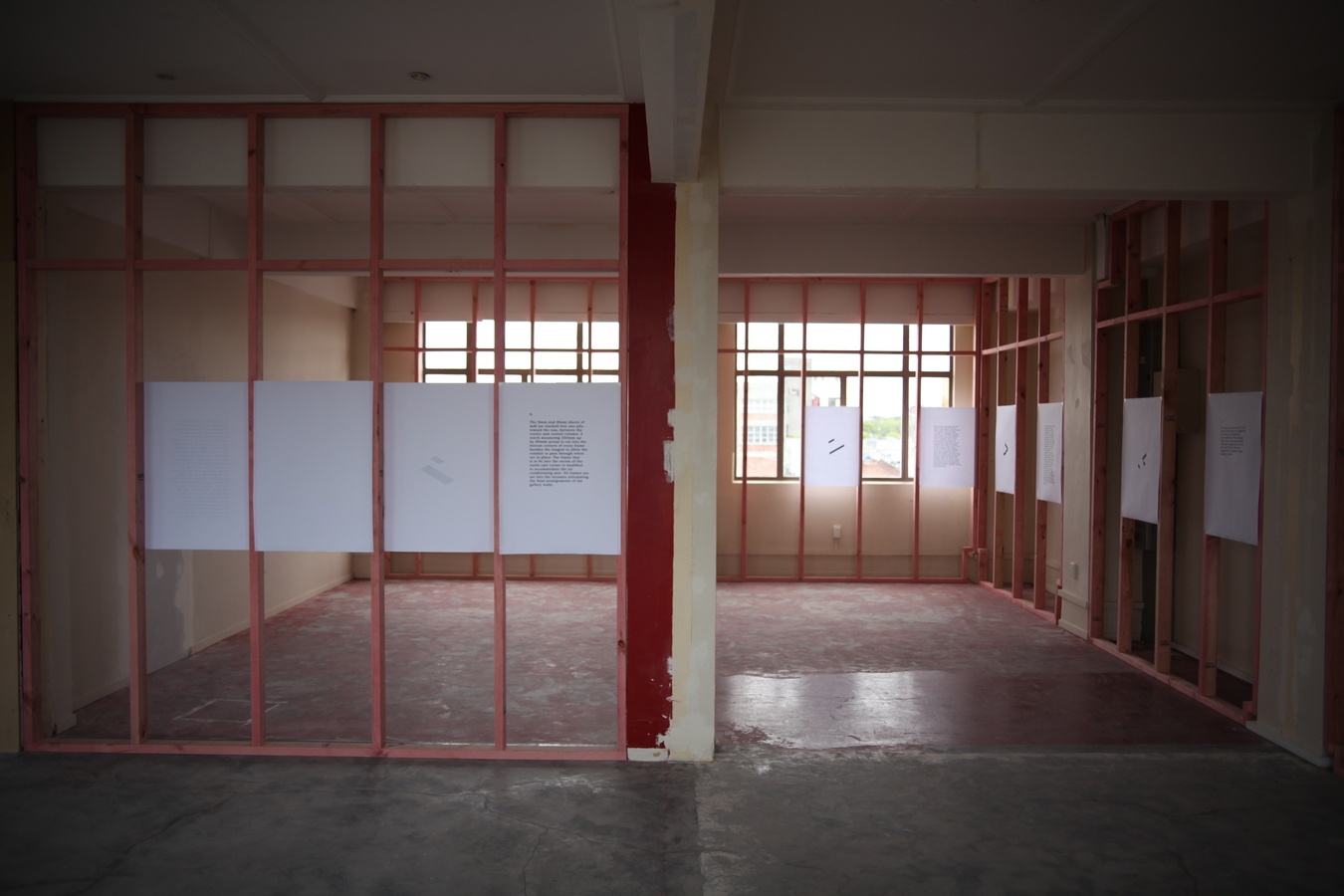
Public Notice #8: 8/12/12
Configuration #8: Final arrangement of the gallery walls.
The 9mm and 18mm sheets of mdf are stacked into one pile, toward the rear, between the corner and central column. A notch measuring 330mm up by 90mm across is cut into the bottom corners of every frame besides the longest to allow the conduit to pass through when set in place. The frame that is to fit into the recess of the north east corner is modified to accommodate the air conditioning unit. All frames are set into the recesses articulating the final arrangement of the gallery walls.